Purpose: The purpose of this part of the lab is to introduce you to the characteristics and uses of the uniaxial flash interference figure and to also show you of additional uniaxial minerals with which you need to become familiar.
On sections of uniaxial minerals cut parallel to the c-axis an interference figure, termed the flash figure can be seen. This figure, the optics of which are described in Bloss page 119, superficially resembles some of the biaxial interference figures you will see in the next lab. However, the isogyres of the uniaxial figure move rapidly out of the field of view on rotation of the stage. Hence the name "flash figure".
Four oriented slides are available for observing well centered flash figure, are labeled "Relief scale". The beryl and apatite are cut parallel to the c-axis. As they become available look at one from each of these two groups so you can answer the questions below.
I. Sketch a uniaxial mineral cut // to c-axis. Assume that it has good basal cleavage and is elongated along the c-axis. Show the c-axis direction, the cleavage, and the vibration directions of the E- and O- rays on your sketch.
II. Now take one of the oriented crystal slides and look at the flash figure. Rotate the slide until the isogyres form a fuzzy cross-like figure centered on the cross-hairs. Now rotate the slide and measure how many degrees are needed to carry the isogyres beyond the field of view. Record the amount of rotation for both directions below.
_____________, ______________
As you rotate the stage the isogyres move from their centered position into the quadrants into which the c-axis is being rotated. Explain how you can use this knowledge of the orientation to determine the optic sign of the mineral. ( Hint, Think of how you can use the mica plate to determine if n > n or n < n ). Using this test, what is the optic sign of the apatite?
III. If a uniaxial mineral is oriented // to the c-axis (i. e shows a centered
flash figure) does it show minimum, intermediate, or maximum interference colors?
Why?
IV. Look at the "Relief scale" slide. Assure yourself that they are
properly oriented to show centered flash figures. What are the maximum interference
seen over most of the beryl crystal? The apatite crystal?
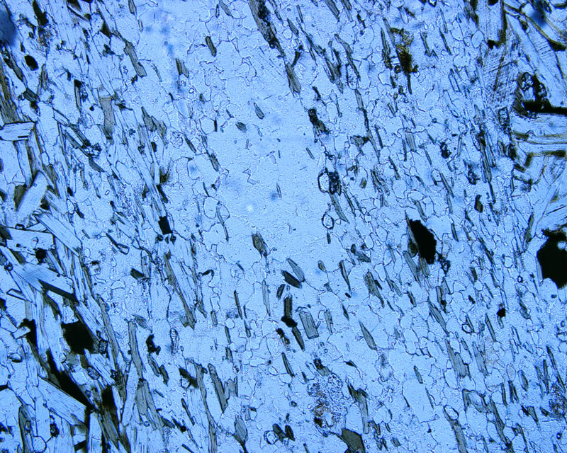
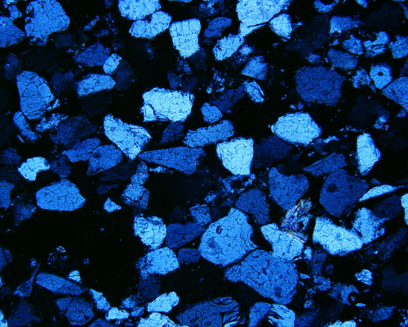
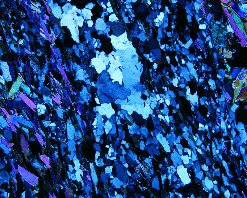
V. Look at one of the slides of quartz-bearing rock BH-250-27 and see if you can find grains in the proper orientation to show a centered flash figure. (hint: are you looking for maximum, minimum, or intermediate interference color?) what do you find for the optic sign of quartz (1,2,3,4,5,6) using the flash figure?