My DIY Analog Modular Synthesizer
Table of Contents
John Ellinger, built 2014-2019
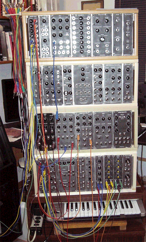
Front
Rear
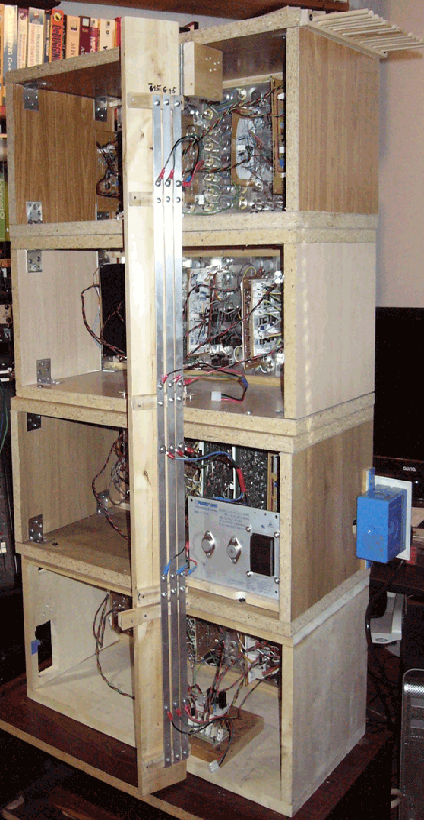
Cabinets 1-4 bottom to top
Cabinet 1
| Quad MIDI CV | 2019 | John Ellinger | Teensy 3.5, DAC8565 |
| MIDI CV | 2015 | John Ellinger | Arduino Uno, MCP7425 |
| CV and Gate Distributor | 2017 | Ray Wilson, MFOS | |
| Multiples | 2015 | Electronotes | |
| ADSR | 2017 | YuSynth | |
| ADSR | 2015 | Thomas Henry | |
| ADSR | 2018 | Digisound 81 | |
| ADSR | 2019 | John Ellinger | AS3310 |
Cabinet 2
| VCO 1 | 2014 | Electronotes | |
| VCO 1 | 2016 | Electronotes | |
| VCO Maximus | 2017 | Thomas Henry | CEM 3340 |
| VCO 555 | 2017 | Thomas Henry | |
| Utility Dual LFO | 2018 | Ken Stone, CGS-58 | |
| Power Supply | 2019 | MeanWell | HBB-15-1.5-A |
Cabinet 3
| Utility LFO | 2015 | Electronotes | |
| VCF 2 | 2015 | Electronotes | |
| Moog Ladder Filter | 2016 | Mod. EFM | |
| Steiner VCF | 2017 | Ken Stone, CGS | |
| Low Pass Filter | 2017 | Pontius/Stites | CEM3328 |
| Wavefolder | 2015 | YuSynth |
Cabinet 4
| Quad VCA | 2018 | John Ellinger | SSM2164 |
| Dual VCA | 2015 | Ray Wilson, MFOS | |
| Mixer | 2015 | Electronotes | |
| Attenuator 8 | 2015 | Ray Wilson, MFOS | |
| Sample and Hold | 2015 | Electronotes | |
| Noise | 2015 | Electronotes | |
| Ring Modulator | 2015 | Electronotes |
Module Test Jig
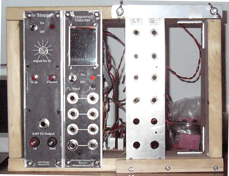
| 8v Stepper | 2018 | John Ellinger | Teensy 3.2 |
| Frequency Counter | 2017 | John Ellinger |
Resources
I found the following resources invaluable while building the synth.
Books
The three Electronotes items below by Bernie Hutchins are the bible of analog synth and musical electronics. Most of the circuits I built are from these sources. I started with the Preferred Circuits Collection and Musical Engineer's Handbook and was so impressed I ordered the complete Electronotes collection.
- Electronotes Complete series (1970-2015)
- Preferred Circuits Collection
- Musical Engineer's Handbook
Hal Chamberlin: Musical Applications of Microprocessors (2nd Edition)
Another excellent source. Out of print but used copies are still available online.
Ray Wilson: Make: Analog Synthesizers
A basic intro to what you need, what's involved, and how to get started.
Web sites
- http://www.musicfromouterspace.com/ [Ray Wilson, MFOS]
- http://search.retrosynth.com/synth-diy/ (The searchable Synth DIY archives)
- http://yusynth.net/Modular/index_en.html [YuSynth]
- http://www.magsmoke.com/thomas_henry_books.asp [Thomas Henry]
- https://www.elby-designs.com/webtek/cgs/cgs.htm
Essential Tools
- Voltmeter
- Power Supply (+15 V, -15 V, 5 V)
- Oscilloscope
- Function Generator
- Soldering Station
- Plus other smaller less expensive items listed in the Ray Wilson book above.
Construction
Most of the modules I built were from schematics that date from the mid 1970's and were designed by Bernie Hutchins as part of the Electronotes ENS-76 series and Musical Engineer's Handbook.
Circuit Design Software
I used the Mac version of the Kicad open source circuit design software design the schematics and layout the PCB.

Every symbol in the schematic has an assigned "footprint." The footprint is the exact shape and dimensions of the actual component accurate to thousandths of an inch that will appear on the printed circuit board (PCB).
When the schematic is complete and passes all design rule checks it can be imported into the PCB designer. I arranged the components on a 0.1 inch grid that has the same spacing as the perforated circuit boards I use.
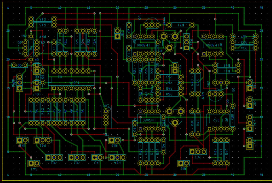
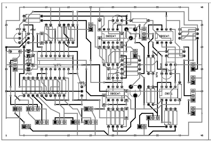
I exported multiple PCB layout files and merged them into a single Adobe Illustrator image that I printed and attached to my circuit board. I poked the component leads through the perfboad holes and followed the wiring diagram with black lines indicate wires on the top of the board and gray lines indicating wires on the bottom of the board.
To double check my work, I printed another copy of the Illustrator diagram, and used a set of multi-colored markers to trace over the diagram while hilighting circuit traces in Kicad. When I was relatively confident I had done things correctly I applied power and tested the circuit. Sometimes it worked on the first try, often it did not and I'd go back to the colored markers, and retrace my diagram against the original schematic. Bernie's schematics were always correct and the errors were always mine, usually recreating the schematic in Kicad. Eventually I got every circuit to work as described.
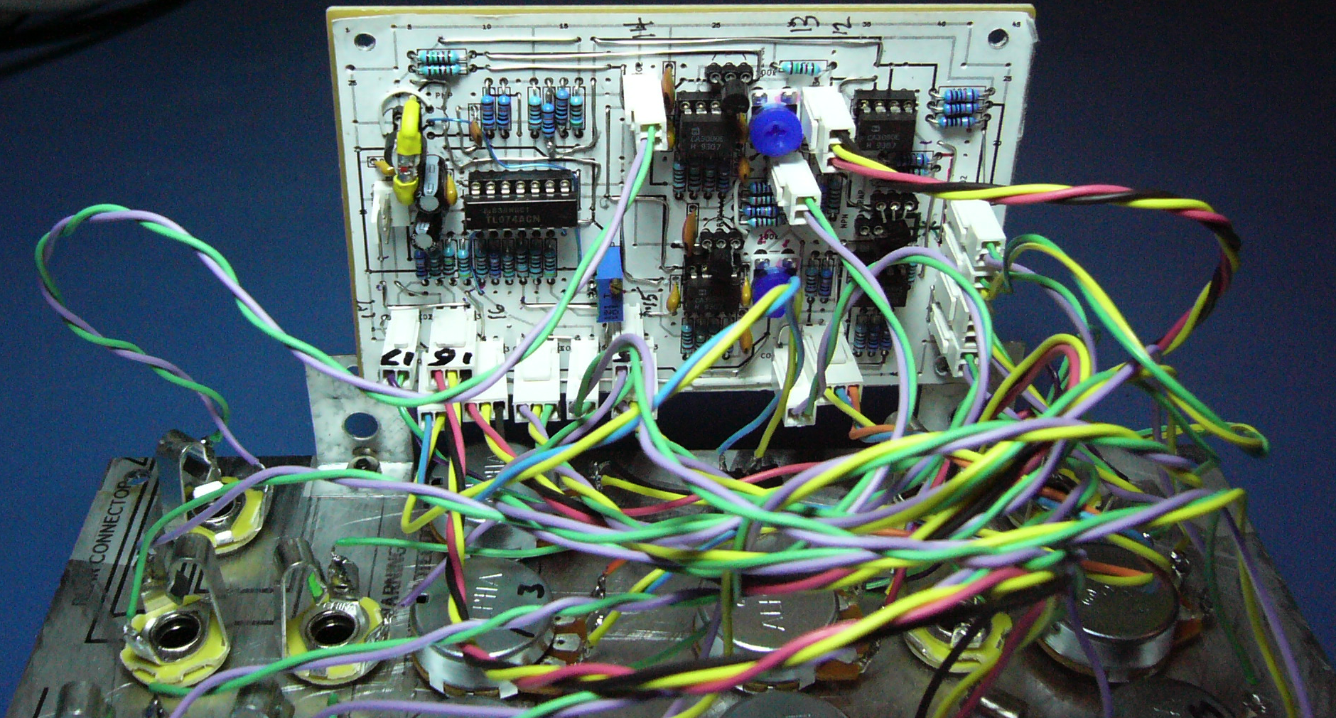
This is the top side of completed VCF module.
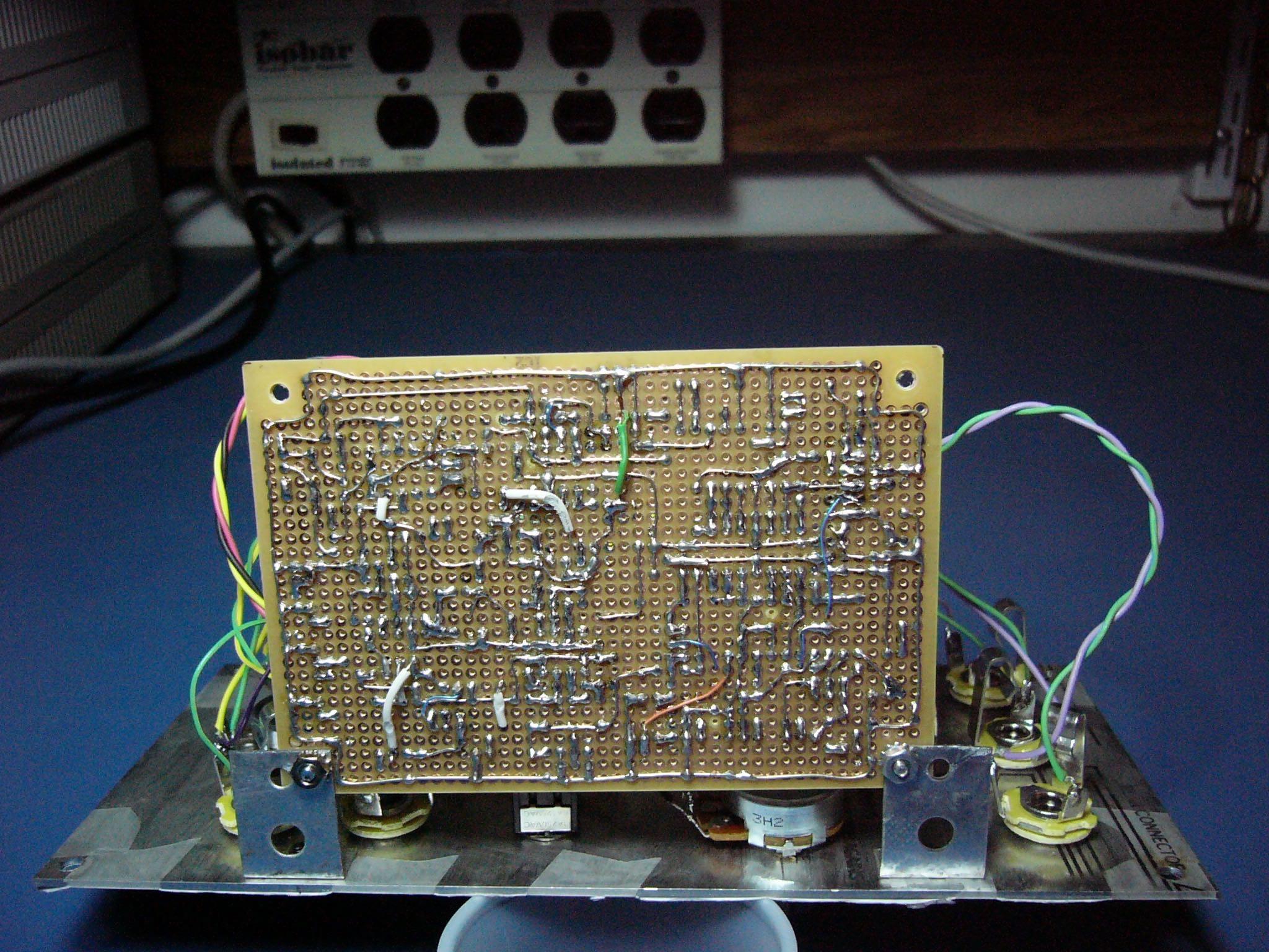
This is the bottom side of the same module.
The faceplate templates were made in Illustrator, taped to a blank aluminum faceplate, drilled to accept the poteniometers and 1/4 inch jacks. A second Illustrator template was printed on ordinary paper and taped to the faceplate. The PCB was mounted at a right angle to the faceplate and the faceplate hardware was wired to the PCB.
The cabinet was constructued using inexpensive shelving and screwed together with right anlgle brackets. The modules were screwed in 1/2 inch wood rails mounted inside the cabinent.
Basic Module Categories
My synth modules fall into these six general categories.
- Input Devices
- MIDI keyboard
Quad MIDI CV
MIDI CV
CV and Gate Distributor - Waveform Generators
- 5 VCO's
Utility VCO
Utility Dual LFO - Amplitude Modifiers
- Quad VCA
Dual VCA
Attenuator 8
Mixer - Envelope Generators
- 4 ADSR's
- Spectrum (Timbre) Modifiers
- 5 VCF's
Wavefolder
Ring Modulator
Noise - Routing
- Multiples Mixer
- Sequencing and Timing
- Sample and Hold Module
Square wave outputs from the VCO's and LFO's.
Voltage Control
Three Basic Signal Voltages are used withing the synth.
- Signal Voltages
- These are bipolar signals ±5 Volts, 10 Volts peak to peak, used to produce the five basic audio waveforms, sine, saw, square, triangle, and pulse.
- Control voltages
- These signals can be either bipolar (±5 V) or unipolar (0-5 V) and are used to modulate (modify) audio signals or other control voltages. Control voltages can be used to modulate the amplitude, envelope, and spectrum of an audio signal without ever touching a dial, knob, or slider.
- Logic voltages
- These are control voltages where a high voltage represents a digital one and a low voltage represents a digital zero. Square waves are ideal for this purpose because of their steady high and low states and fast transitions between the states.
The VCO can generate all three types: signal voltages for audio waveforms, control voltages that are sent to to a VCA or VCF to modify an audio signal, or logic voltages using it's square wave output.
What is a Voltage Controlled Oscillator?
It's an oscillator whose frequency will increase or decrease by applying a control voltage. Musical oscillators are calibrated so that a one volt change in control voltage will produce a one octave change in frequency. That means an eight octave synthesizer will need an eight volt range. Oscillators can play every pitch on the piano as well as a continuous range of frequencies between each note. In equal temperament the notes 12 notes within an octave on the piano are equally spaced in frequency related the 12th root of 2. A VCO needs a precise 1/12 of a volt change (83.3 millivolts) fore each half step. Oscillators also produce frequencies below and above the range of human hearing.
AC voltage, DC voltage, and DC Bias
- DC (Direct Current) voltages produce a steady voltage at a specific level. 10 volt DC ranges from 0 to 10 volts.
- AC (Alternating Current) voltages produce a voltage that wanders above and below a centerline. 10 volt AC ragnes from -5 to +5 volts.
- DC Bias refers to how far the centerline of AC is above or below zero volts. 10 volt DC with a -2 volt Bias ranges from -2 to 8 volts.
Power Supply
The most basic component of the synth is the power supply. Without it, nothing works. It's buried inside the cabinets with wires distributed to each module to provide the correct voltage and current to power the circuits. Power supplies take the 110 V AC from the wall plug and use transformers and a few other components to create the required circuit voltages. The most common voltages used in analog synthesizer circuits are ±15 V AC and +5 V DC.
My current power supply is the MeanWell HBB-15-1.5-A. It supplies ±15 volts. I tap the +15 off to a separate pcb 5 volt supply based on the LM7805.
MIDI to CV
The two MIDI to Control Voltage modules are my own design combining several references from the web.
They both use a standard MIDI input circuit using th 6n138 optio-isolator.
My first MIDI to CV converter has a single input uses an Arduino programmed chip to receive the MIDI note number played on the keyboard. That note number represents frequency. The number is scaled by a 12 bit DAC (Microchip MCP4725) that converts number to a voltage in a range of 0 - 5 Volts. That voltage is then scaled using an OpAmp to the range required by the VCO for semitone steps. The Atmega 328p also outputs a 5 volt gate and trigger signal to the envelope generator.
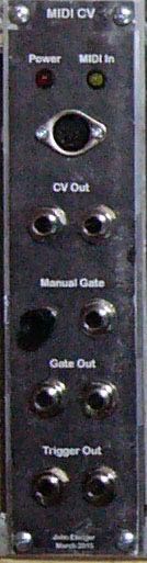
- CV Out
- (Control Voltage) is patched to the one volt per octave input on the VCO and determines the frequency of the note played.
- Gate Out
- A gate is a long 5V pulse that begins when a MIDI key is pressed and continues until the MIDI key is released.
- Trigger Out
- A trigger is a very short 5V pulse that signals the beginning of a note and is sent whenever a MIDI key down is pressed down.
A simple MIDI In circuit receives the Note On MIDI command that is sent to an Atmel 328P (Arduino) chip that determines the MIDI note number of the key pressed. The 328P then sends the note number to a 12-bit DAC chip that determines the voltage required to produce that frequency. Note Off and all other MIDI messages are ignored.
The 88 keys on a piano keyboard are mapped to MIDI note numbers 21-108 (A0 - C8). The range of the 12 bit DAC is 4096 (2^12) values spread over 5 volts. Each MIDI note number would be 46.5 (4096/88) DAC units apart. I wrote Arduino code to convert every MIDI note number to evenly spaced DAC values. Because VCO circuits are designed so that a one volt change will result in a one octave change in frequency and because MIDI keyboards are tuned in equal temperament the 12 half steps within an octave are each 1/12 V (83 mV) apart. Additional code code scales the 5 volt DAC output to the 8 volts needed for an 8 octave VCO.
My second MIDI to CV converter has four inputs and uses a dac8565 four channel dac. This converter can receive MIDI channels 1-4 and output a control voltage for pitch and a gate signal for the envelope for each channel.
MIDI CV Patch to control the frequency of the Oscillator
MIDI Controller Input => MIDI CV Input
MIDI CV CV Output => VCO 1V/Oct Input
VCO Waveform Output => VCA In => Speakers
Problems
If you play the same key twice you won't hear the second one. Notes never turn off.
VCO
The Voltage Controlled Oscillator is the VCO1 design by Bernie Hutchins from the ENS-76 series.
The The VCO generates five basic audio waveforms.
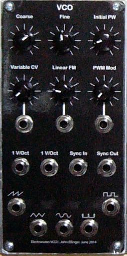
VCO stands for Voltage Controlled Oscillator and can generate a continuous range of frequencies proportional to the applied input voltage. A voltage controlled audio oscillator can produce continuous frequencies from 0.01 Hz to over 20,000 Hz, while the 88 keys on an full piano keyboard only produce evenly spaced discrete frequencies from 27.5 Hz to 4186 Hz.
VCO voltage structure
Most VCO circuits are designed so that a one volt change will result in a one octave change. A VCO with a 10 volt range will span 10 octaves. The highest C on the piano, C8, is in the eighth octave at a frequency of 4186 Hz. The 9th octave C would reach 8372 Hz, and the 10th octave C would reach 17,464 Hz. Many early synthesizer keyboards were limited 3 to 5 octaves.
Tuning the VCO
Play Middle C on the keyboard and adjust the VCO Coarse and Fine controls until you have a frequency of 261.6 Hz.
The Five VCO Waveforms
This VCO produces five basic waveforms: sine, saw, square, triangle, and pulse with variable duty cycle. Each of these waveforms can be described mathematically as a sum of harmonically related sine waves as part of a Fourier Series.
The Fourier Series
The basic premise of Fourier's theorem states that: any continuous periodic waveform can be transformed into the sum of simple sine and cosine waves of varying amplitudes and phases at integer multiples of a fundamental frequency. The following formulas are from the Musical Engineer's Handbook by Bernie Hutchins. http://electronotes.netfirms.com/
Sine Wave

Sawtooth Wave

Square Wave

Triangle Wave

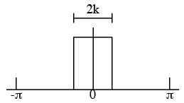
Pulse Wave

The VCO output is usually connected to a VCF or VCA input.
Pulse Wave Duty Cycle The percentage of time the pulse is high relative to the total period is called the duty cycle. A square wave has a 50% duty cycle. Changing the duty cycle changes the spectrum (timbre) of the waveform.
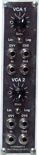
Dual VCA
The Dual Voltage Controlled Amplifier is a Ray Wilson design from the Music from Outer Space web page.
This is the final output stage before going to the speakers.
The Simplest Patch Possible
VCO output to VCA input then VCA output to speakers.
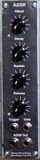
ADSR
The Attack Decay Sustain Release envelope generator is a Thomas Henry design from his book: An Analog Synthesizer for the 21st Century.
The Attack Decay Sustain Release (ADSR) envelope generator is the solution to notes turning off and re-articulation. It has four knobs that control the four segments of an ADSR envelope.
 …
… 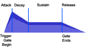
The envelope segments in analog synthesizers are exponential curves rather than straight lines. These curves are naturally produced by charging and discharging a capacitor.
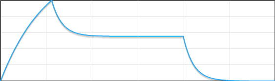
http://www.earlevel.com/main/2013/06/23/envelope-generators-adsr-widget/
The Trigger and Gate outputs from the MIDI CV module are used as gate and trigger inputs to ADSR. The attack and decay segments respond to the trigger, the sustain remains in effect as long as the gate is high (5V) and the release segment begins when the gate ends. Four knobs (potentiometers) control the duration and level of the of the four segments.
ADSR Patch
MIDI Controller Input => MIDI CV Input
MIDI CV CV Out => VCO 1V/Oct Input
MIDI CV Trigger => ADSR Trigger Input
MIDI CV Gate => ADSR Gate Input
ADSR Output => VCA CV1 Input
VCO Waveform Output => VCA In => Speakers
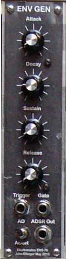
Env-Gen
The Envelope Generator is a Bernie Hutchins design from the ENS-76 series.
It has an Attack Decay (AD) output and an ADSR output.
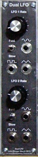
Dual LFO
The Dual Low Frequency Oscillator was adapted from a single LFO design by Bernie Hutchins from the ENS-76 series.
The Low Frequency Oscillator can produce infrasonic waveforms below the range of human hearing as well as audible low frequency sounds. Even though you cannot hear many of the LFO waveforms, they are useful as modulation sources to produce tremolo and vibrato effects. There are two identical LFO's in this module.
Tremolo
Tremolo is created by small changes in amplitude
- Experiment
- Remove Trigger and Gate so there is continuous sound.
LFO Sine Input (Switch set to Slow) => VCA CV2.
Sweep LFO Rate. Notes are either on or off which is "maximum depth of modulation".
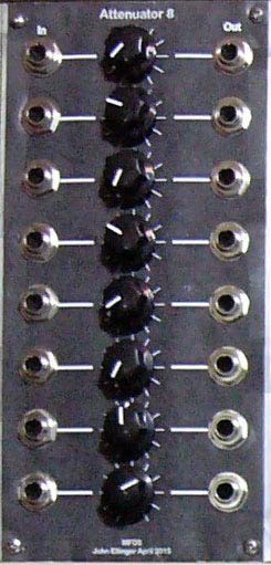
Attenuator 8
The Attenuator 8 is a Bernie Hutchins design from the Musical Engineer's Handbook.
Eight inputs on the left, eight outputs on right with gain/attenuation potentiometers for each pair.
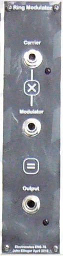
Ring Modulator
The Ring Modulator is a Bernie Hutchins design from the ENS-76 series.
Ring modulation is similar to AM modulation in that it produces sidebands related to the carrier and modulator frequencies. The difference is the carrier frequency disappears.
Remember the basic wave equation

If A is another sinusoidal wave of the following identity holds, resulting in the sidebands. Note that neither frequency x or y is present.

Utility VCO
The Utility Voltage Controlled Oscillator is a Bernie Hutchins design from the ENS-76 series
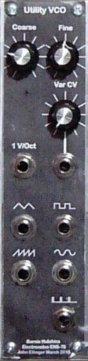
The utility VCO is similar to the main VCO but has fewer features and is less precise.
Tremolo patch (Amplitude Modulation)
Tremolo - small variations in amplitude. Experiments 1 and 2 are examples of AM Modulation
LFO Sine Input (Switch set to Slow) => Attenuator 8 any input
Attenuator 8 output => VCA CV2
- Experiment 1
- Sweep the LFO Rate while adjusting Attenuator gain
The gain controls the "index of modulation".
Set LFO Switch to fast and sweep to highest rate. Slight roughness occurs.
Demo 7 Hz vibrato from Noise module - Experiment 2
- Increase the Frequency of the Tremolo
Set Utility VCO Coarse and Fine Controls to minimum.
Utility VCO Sine Output => VCA CV2 Input
Sweep the Fine control to 12:00
Sweep the Coarse control and observe the sidebands that appear in the spectrum output. The fundamental frequency is still present with sidebands equal to plus and minus the modulator (Utility VCO) and carrier (VCO) frequencies. Attenuator 8 gain still controls the depth of modulation.
Vibrato patch (Frequency Modulation)
Vibrato - small variations in frequency Experiments 3 and 4 are examples of FM Modulation
- Experiment 3
- Set Utility VCO Coarse and Fine controls to minimum.
Utility VCO Sine Out => VCO Linear FM Input
Observe changes in frequency without changes in amplitude
Connect MIDI CV and ADSR
Change Octave switch while playing C's - Experiment 4
- Utility VCO Sine Out => VCO Linear FM Input
Change Utility VCO Coarse control listen for metallic and drum sounds.
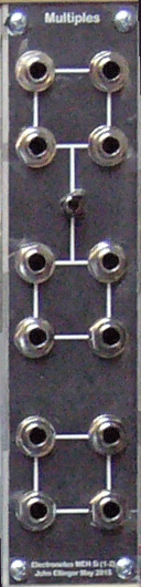
Multiples
The Multiples module is a Bernie Hutchins design from the Musical Engineer's Handbook.
Each square of 4 jacks can be used in various ways for routing signals: 1 in 3 out, 3 in 1 out. The upper and middle group of four is connected by a toggle switch that in one position is an 8 jack multiple and in the other are two indpendent 4 jack multiples.
Wavefolder
The Wavefolder is a Yves Usson [YuSynth] design.
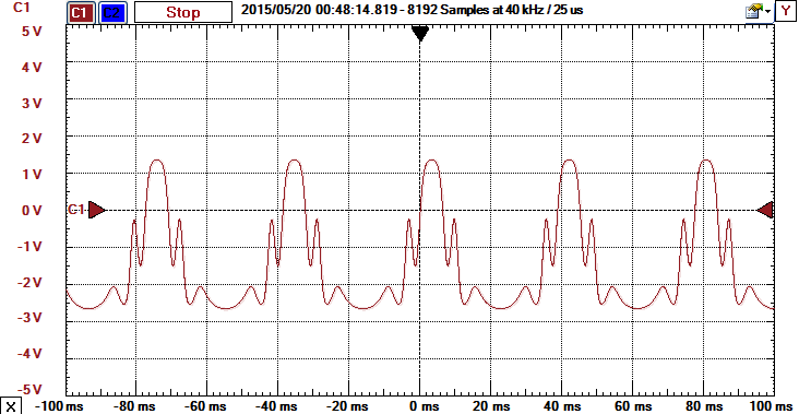
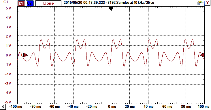
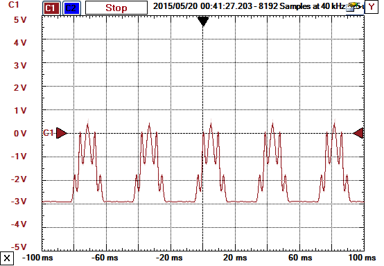
This module adds additional harmonics to a basic waveform by, an example of Timbre modification.
Here's a sine wave modified by the Wavefolder.
VCF
The Voltage Controlled Filter is the VCF2 design by Bernie Hutchins from the ENS-76 series.
The circuit in this Voltage Controlled Filter is called a state variable filter and offers three simultaneous outputs: a Low Pass Filter, a Bandpass Filter, and a High Pass Filter.
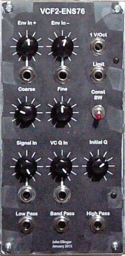
Q or Resonance
A feature on many VCF's is a Q or resonance control. The Q can be manually changed with a knob or voltage controlled from an Envelope, VCO, or LFO.
- Low Q
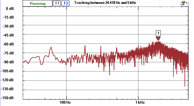
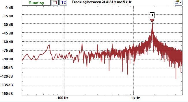
- High Q
Patch to automate the bandpass sweep
LFO Triangle => Filter Envelope+
You can sweep through the harmonic series
Patch to slowly sweep through the harmonic series
VCO Saw => VCF Signal In (Medium High Q)
If you turn the Coarse control slowly you can count the harmonics
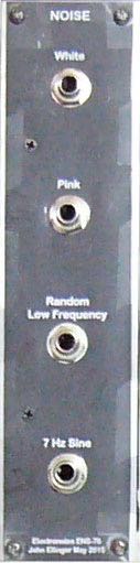
Noise
The Noise module is a Bernie Hutchins design from the ENS-76 series.
The Noise module can add grit to a sound. It can also be fed to the input of a Sample and Hold module to produce the sci-fi sounds similar to those heard in movies showing early computers.
Sample And Hold
The Sample and Hold module is a Bernie Hutchins design from the ENS-76 series.
The Sample and Hold module functions as a random note player with Noise as an input. Science fiction movies of the 1950s used these sounds to indicate their "advanced" computers were working on a problem.
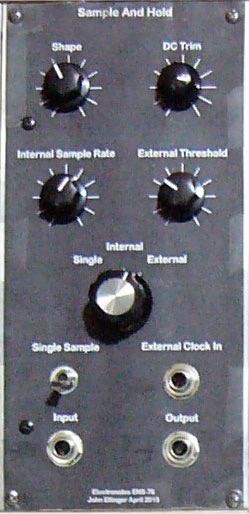
The Shape knob controls the output pitch range.
The DC Trim knob adjusts the frequency range up or down.
The Internal Sample Rate knob controls the speed of the output.
The Output jack is connected to a VCO waveform.